Temporary prototype to permanent prototype!
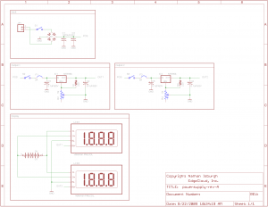
Posted in Power Supply on October 12th, 2009 by nisburgh – Be the first to commentNow that I had a working system, I needed to make it a little more permanent. First of all, I wanted dual outputs, so here’s the new schematic I put together.
You’ll notice that the voltmeters are run off a separate battery. This frustrated me to no end. Basically, most digital voltmeters *require* an isolated power supply. You can get high end units that self isolate, but they’re about $100 each. I wanted digital for accuracy ( this problem only affects digital VM’s – analog would have worked as is ), so I just decided to go with the battery option and see how long it lasts. I’d be curious what it might have taken to separate off a 9V supply and isolate it from the variable outputs.. I messed with it for a while, but the closest I got was a voltmeter with a pretty heavy bow in it’s accuracy curve. ![]()
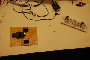
Anyhow, off to Radio Shack and Fry’s for a few more pieces! Proto board, plastic enclosure and extra parts to build a dual output power supply. After I cut the board down and drilled mounting holes, I started moving components from the breadboard to the more permanent proto board. Here’s a shot shortly after starting to solder. I mostly used the long leads from the components to bridge everything together. It’s not the prettiest option, but the cost/speed beats a one-off custom PCB. Note the beefy heatsinks for the regulators. An absolute must! I was reading 145 °F on the heatsink just powering a stamp, LCD and PING))) sensor.
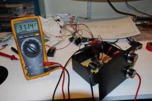
After a couple hours of soldering, fabrication and connecting parts, I had the beginnings of a working lab supply!
Up next, switches, voltmeters and binding posts!
Fresh Toys!!
Posted in Electronics on October 8th, 2009 by nisburgh – 2 CommentsMy first order from Sparkfun came in!
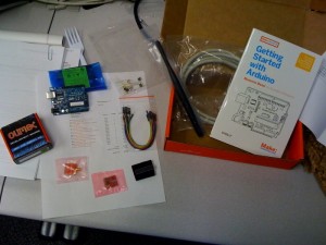
Here’s the box, surprisingly not damaged in shipping! Congrats, Fed-Ex!
More importantly, here’s what was in the box!
Great Horned Owl
Posted in Animals on October 8th, 2009 by nisburgh – Be the first to commentI love owls. Came across these photos of a Great Horned Owl this morning and wanted to share them. ![]()
Music machine
Posted in Interesting, Recommendations on October 5th, 2009 by nisburgh – Be the first to commentWater Detection Circuit
Posted in Projects on October 4th, 2009 by nisburgh – Be the first to commentSo one of the first sensors I would like to implement for the sensor mesh is a simple water detector. You know, for washer machines, refrigerators, water heaters, etc. Let’s you know when you’ve got a leak. I wanted the circuit to be simple and low power, since it would almost certainly be run off a battery, and the RF gear alone was going to suck most of the available juice. I also wanted a circuit external to the microcontroller to remember ( latch! ) if we had a leak condition, that way I could let the microcontroller and RF module sleep for a few minutes between checks, but still capture transient leak conditions ( What if a droplet hit the sensor, but then rolled off due to slope? ).
Anyhow, water is not nearly as conductive as you would think. Rudimentary testing of water droplets indicated about 200k-500k of resistance. My first, simple attempt at a water detection circuit did not take this into consideration.
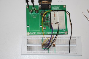
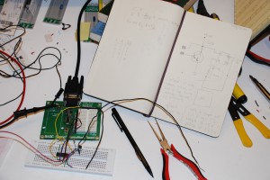
Here’s a snapshot of the test circuit I built. It works great using that little tactile switch. But it doesn’t have the capability to pull the S input on the S-R flip flop to ground when running through water. That’s simply because the path to ground for the VCC pullup has too high a resistance ( 200k-500k through water ) to drop the voltage below 0.8V, necessary for a TTL low signal. I didn’t bother putting together an eagle schematic for this design since it didn’t work. ![]()  The astute will notice I don’t actually have it wired up to an R-S flip flop ( 74279 ). I didn’t have one on hand, so I built one with a 7400 I had in stock.
 The astute will notice I don’t actually have it wired up to an R-S flip flop ( 74279 ). I didn’t have one on hand, so I built one with a 7400 I had in stock.
At his point, I figured that I needed some amplification of the current I was able to push through a drop of water, so obviously a transistor came to mind. A standard NPN transistor ( 2N2222 ) wouldn’t do, though, since it doesn’t provide adequate amplification of the base current produced by 5V pushing across 200k-500k resistance. What I needed was a Darlington transistor! Amplify the amplification!
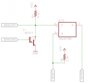
Here’s the circuit I put together using a Darlington NPN transitor to amplify the current that could be pushed through a drop of water at 5VDC. When the power turns on, the microcontroller needs to reset the S-R flip flop by cycling the Reset line low then hold it high. We have the S-R flip flop to “remember” when we have a moisture condition for the sleeping microcontroller. The S input has a pullup resistor R1 just because it’s bad practice to leave a TTL input floating. We connect that same signal to one end of our sensor probe ( SENSOR1 ), as well as the collector on our Darlington, T1. The other side of our sensor ( SENSOR2) connects to the base of T1. If we can push a mere fraction ( think millionths ) of an amp through that sensor, the Darlington is going to open up and dump all of the collector current through it’s emitter into ground. This will draw the S input to ground, flipping the water signal on. The water signal will not turn off until the Reset line ( R on the S-R flip flop ) is pulled low by the microcontroller. Speaking of which, R2 is a pullup to make sure we don’t accidentally reset the flip flop during sleep/wake-up cycles, because on some microcontrollers, like the Stamp used here, the pins switch to inputs for 18 ms until the interpreter takes control.
I put this design together and tested it – it couldn’t work better!  In fact, it’s able to detect the microamps that were able to push through my *body*. The Hfe on the BC517 Darlington is 30k. *Serious amplification!* Now I had a simple circuit that could remember a closed condition ( leak ) and could detect current flowing through megaohms ( necessary for detecting the presence of water ). Mission accomplished.
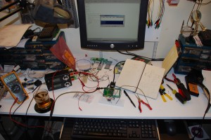
Here’s a final shot of my work area. Prototype, circuit, Jack Daniels, power supply, mess and all!
Nordic Semiconductor
Posted in Recommendations on October 2nd, 2009 by nisburgh – Be the first to commentThese guys have some *awesome* integrated RF products. I’m looking very closely at their nRF24LE1. The XBee is out.
Linx Technologies
Posted in Recommendations on October 1st, 2009 by nisburgh – Be the first to commentThese guys have some great RF modules. I need to dig into FCC regulations a bit more to understand if I can use them in my projects ( sensor mesh networks ).

